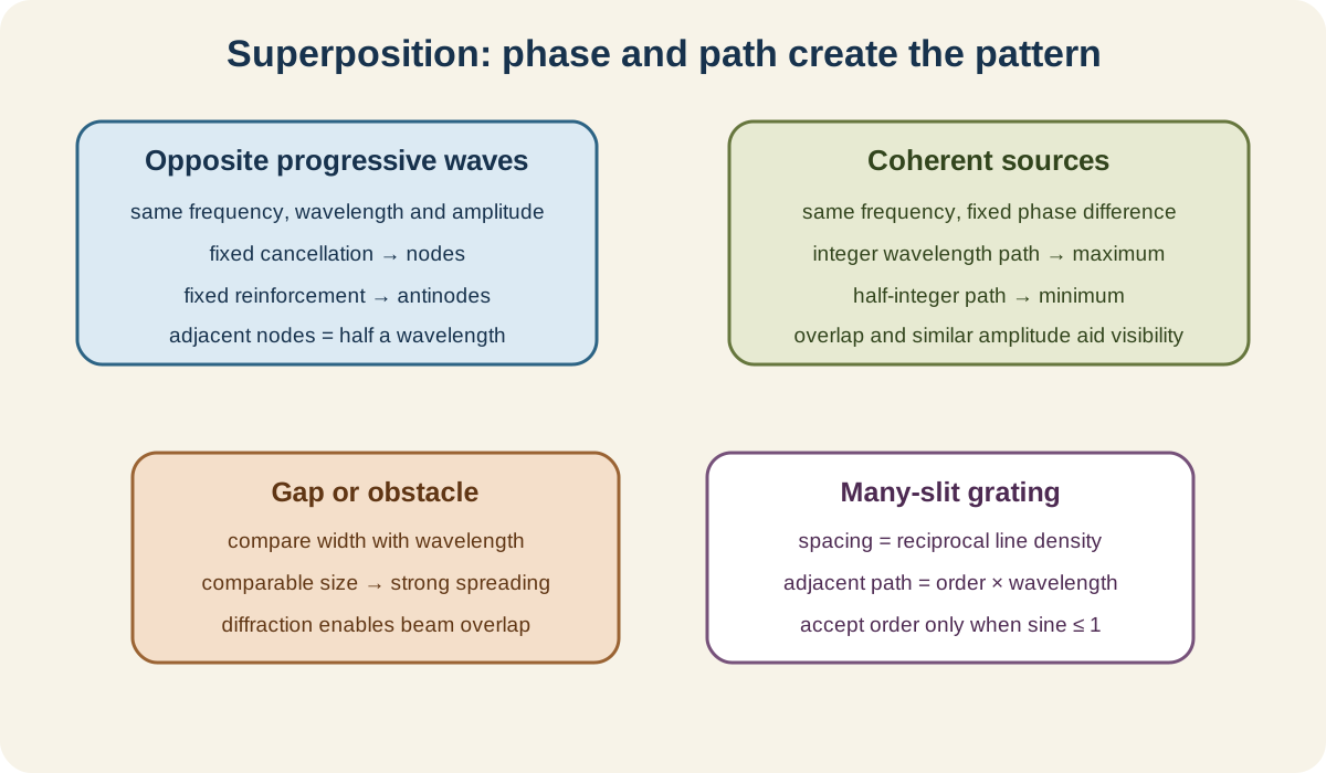
Superposition is Topic 8 of the Cambridge International AS and A Level Physics 9702 AS Level syllabus. The official boundary covers stationary waves, diffraction, coherent two-source interference and diffraction gratings in sections 8.1 to 8.4. The unifying idea is that overlapping waves combine by displacement while retaining evidence of phase and path difference.
8.1 Stationary waves
Principle of superposition
When waves overlap, the resultant displacement at any point and instant is the vector or signed sum of the individual displacements:
yresultant=y1+y2+⋯.
Check this topic from memory
Attempt the matching topic bank before reopening the notes. Use each missed idea to decide what to review next.
Superposition adds displacement, not amplitude magnitudes regardless of sign. Two positive displacements reinforce; positive and negative displacements can partly or fully cancel.
After overlapping in a linear medium, progressive waves continue with their original form. They do not permanently destroy each other.
Constructive interference occurs when waves arrive in phase. Destructive interference occurs when they arrive in antiphase, provided their amplitudes allow cancellation.
Formation of a stationary wave
A stationary wave forms when two progressive waves of the same frequency, wavelength and amplitude travel in opposite directions and superpose.
It often arises from an incident wave and its reflection. Their relative phase changes with position, producing fixed nodes and antinodes.
A node has zero displacement at all times because the two component waves always cancel there. An antinode has maximum oscillation amplitude because the components reinforce.
All particles between adjacent nodes oscillate in phase. Particles in neighbouring loops oscillate in antiphase.
The pattern does not transfer energy along the medium overall. Each component progressive wave carries energy, but their equal opposite fluxes give no net transfer.
Graphical formation
Draw the two component-wave displacements at the same instant and add their ordinates point by point. Repeat a quarter-cycle or half-cycle later.
Node positions stay fixed. Antinode displacements change through zero and reverse sign, so a stationary wave is not simply a frozen curve.
The separation between adjacent nodes is
2λ.
The separation from a node to its nearest antinode is λ/4.
Measure across several node or antinode intervals and divide by their number to reduce fractional uncertainty.
Microwaves
Direct microwaves toward a metal reflector. The incident and reflected waves superpose. Move a detector along the line between transmitter and reflector.
Alternating signal maxima and minima mark antinodes and nodes of the electric field pattern. Adjacent minima or maxima are separated by λ/2.
Keep transmitter, detector and reflector aligned. Reflections from surrounding objects can distort the pattern.
The detector reading represents wave intensity or field response, not a material particle's visible displacement.
Stretched strings
A vibrator drives a stretched string while the far end reflects waves. At resonant frequencies, a clear stationary pattern forms.
For a string fixed at both ends, both ends are nodes. If length L contains n half-wavelength loops:
L=n2λ.
Frequency can be adjusted until stable loops appear. Count half-wavelengths and use v=fλ if wave speed is required.
Increasing tension changes wave speed and therefore resonant frequencies, but the exact speed-tension formula is not needed unless supplied by other content.
Air columns
Sound waves reflect at the ends of an air column and can form longitudinal stationary waves. Describe nodes and antinodes using air-particle displacement or pressure, and do not mix the two representations.
At a closed end, air-particle displacement is a node and pressure variation is an antinode. At an ideal open end, air-particle displacement is an antinode and pressure variation is a node.
For a tube open at both ends, the fundamental length is approximately λ/2. For a tube closed at one end, the fundamental length is approximately λ/4.
The syllabus assumes end corrections are negligible. Do not introduce an end-correction calculation.
Resonance can be detected by maximum loudness or microphone signal as column length or frequency changes.
8.2 Diffraction
Meaning and conditions
Diffraction is the spreading of a wave as it passes through a gap or around an obstacle.
All waves can diffract. The effect is most noticeable when the gap width or obstacle size is comparable with the wavelength.
For a gap much wider than wavelength, wavefronts remain mostly straight with limited spreading near the edges. When gap width is comparable to wavelength, the emerging wavefronts spread widely. A very narrow gap behaves approximately like a point source.
Diffraction does not require two waves or two sources. It is not the same as refraction, which involves a speed change at a boundary.
Ripple-tank evidence
Generate straight water-wave fronts and direct them toward an adjustable gap. Use a strobe or overhead illumination to observe wavefronts.
Keep frequency and water depth constant, so wavelength remains controlled, then compare patterns for different gap widths.
Strong diffraction gives nearly semicircular wavefronts beyond the gap. Wider gaps relative to wavelength produce less angular spread.
Alternatively, hold gap width fixed and lower frequency if wave speed remains approximately constant; wavelength rises and diffraction becomes more pronounced.
Record the ratio of gap width to wavelength rather than only saying the gap is small.
8.3 Interference
Interference and coherence
Interference is the variation in resultant amplitude or intensity produced when waves superpose.
Coherent sources maintain a constant phase difference and have the same frequency. Coherence is necessary for a stable interference pattern.
Independent light bulbs do not produce stable fringes because their phase relationship changes rapidly. Splitting one source into two paths creates coherent secondary sources.
Similar amplitudes give high-contrast maxima and minima. Equal amplitudes are required for complete destructive cancellation, but not for an observable pattern.
Path and phase difference
For two coherent in-phase sources, constructive interference occurs when path difference is
Δr=nλ,
where n is an integer.
Destructive interference occurs when
Δr=(n+21)λ.
If the sources begin with a phase difference, include it when deciding the resultant phase at the observation point.
Path difference is not the sum of the two path lengths. It is their difference.
Water-wave experiment
Drive two ripple-tank dippers from one vibrator so they have the same frequency and fixed phase relationship.
Circular waves overlap. Lines of large amplitude are constructive antinodal lines; lines of little or zero amplitude are destructive nodal lines.
Changing source separation or wavelength changes the angular spacing of these lines.
Use shallow uniform water and stable source amplitude. Reflections from tank walls can add unwanted interference.
Sound and microwave experiments
Two coherent loudspeakers driven by the same signal generator create alternating loud and quiet positions as a microphone or observer moves across the field.
Sound minima may not be silent if amplitudes differ or reflections contribute.
For microwaves, split one transmitter signal or use a two-slit arrangement, then move a detector across positions of maxima and minima.
Keep source phase stable and detector orientation consistent. Microwave reflections from nearby metal objects can alter readings.
Light double-slit experiment
Illuminate two narrow slits with one monochromatic source. The slits act as coherent secondary sources and produce bright and dark fringes on a distant screen.
For small angles and screen distance D much larger than slit separation a:
λ=Dax,
where x is adjacent fringe separation.
Measure across many fringe spacings and divide by the number. Use the centre-to-centre slit separation and slit-to-screen distance.
Increasing wavelength or screen distance increases fringe separation. Increasing slit separation decreases it.
White light produces a central white fringe with coloured fringes nearby because different wavelengths have different spacing, but monochromatic light is used for precise measurement.
Conditions for visible fringes
The sources must be coherent, have the same frequency and maintain a stable phase difference. Their waves must overlap at the observation region.
For light, use the same polarisation direction; orthogonally polarised waves do not form the same intensity fringes at an ordinary screen.
Comparable amplitudes improve visibility. Narrow slits diffract the light sufficiently for the two beams to overlap.
The apparatus must remain stable because tiny path changes shift optical phase.
8.4 The diffraction grating
Grating equation
A diffraction grating has many equally spaced parallel slits. Principal maxima occur when adjacent-slit path difference is an integer wavelength:
dsinθ=nλ.
Here d is grating spacing, θ is angle from the undeviated central direction and n=0,1,2,… is order.
If the grating has N lines per metre:
d=N1.
Use lines per metre, not lines per millimetre, unless converted.
The central maximum is order zero. Orders occur symmetrically on both sides for normal incidence.
An order exists only if nλ/d≤1. This sets the greatest possible order.
Determining wavelength
Illuminate a grating normally with monochromatic light. Identify the central maximum and corresponding order maxima on both sides.
Measure the angle θ for a known order, calculate grating spacing from its line density and use λ=dsinθ/n.
Measure both left and right angles and average their magnitudes to reduce alignment error. Use higher orders when well resolved because larger angles can reduce fractional angular uncertainty, but ensure the order exists and is correctly identified.
The detailed structure and use of a spectrometer are outside the syllabus. The required method is the grating geometry and wavelength calculation.
Many slits produce narrow, intense principal maxima, improving angular resolution compared with two slits.
Worked application: checking fringe and grating evidence
Light produces double-slit fringes with a=0.30mm, D=2.0m and x=4.0mm. Thus λ=ax/D=6.0⋅10−7m. A grating has 500 lines per millimetre, so d=1/(5.00×105)=2.00⋅10−6m. For the same light in second order, sinθ=2λ/d=0.600, giving θ=36.9∘. Third order remains possible because 3λ/d=0.900, but fourth order is impossible because its sine would exceed one. The existence check accepts every physical order and rejects the first impossible one.
Common misconceptions and corrections
Adding wave amplitudes without signs. Superpose instantaneous displacements.
Saying waves disappear after destructive overlap. They continue through a linear medium.
Calling every interference minimum a stationary-wave node. A stationary pattern needs opposing matched waves.
Saying a stationary wave transfers energy along its pattern. Net transfer is zero.
Calling a node a point momentarily at zero. It remains zero at all times.
Saying antinodes are fixed displaced points. Their displacement oscillates.
Using adjacent node spacing as wavelength. It is half a wavelength.
Using node-to-antinode spacing as half a wavelength. It is one quarter.
Saying neighbouring loops are in phase. They are in antiphase.
Mixing pressure and displacement nodes in an air column. They exchange roles.
Adding end corrections. They are explicitly excluded.
Calling diffraction reflection. Diffraction is spreading.
Saying only water waves diffract. All wave types can.
Claiming the widest gap gives the most diffraction. Compare gap width with wavelength.
Calling diffraction strongest only when the gap is zero. A transmitted wave needs an opening.
Calling interference any crossing of waves. It is the resultant variation produced by superposition.
Defining coherence as equal amplitude. It requires same frequency and constant phase difference.
Using two independent bulbs as coherent sources. Their phase difference is unstable.
Calling path difference the total path length. It is the difference between paths.
Using integer wavelengths for destructive interference from in-phase sources. That is constructive.
Requiring equal amplitudes for any fringes. They are needed only for complete cancellation.
Ignoring overlap of the two beams. No common region means no fringes.
Using slit width as a in the double-slit formula. Use slit separation.
Using total pattern width as one fringe spacing. Divide by the number of intervals.
Applying λ=ax/D without the distant-screen approximation. Its derivation uses small angles.
Saying increasing slit separation widens fringes. It narrows them.
Using grating line density as spacing. They are reciprocals.
Leaving lines per millimetre unconverted. Convert to lines per metre.
Measuring grating angle from the grating surface. Measure from the central direction or normal.
Calling the central maximum first order. It is zero order.
Using degrees directly inside an algebraic sine without calculator mode awareness. Confirm angle units.
Accepting an order with sinθ>1. That order cannot exist.
Saying higher order always exists. Wavelength and spacing impose a maximum.
Describing spectrometer internals as required content. They are excluded.
Assessment guidance
Begin with signed displacement superposition and identify the phase condition before naming constructive or destructive interference. For stationary waves, state the two opposing component-wave conditions, distinguish nodes from momentary zero displacement and convert repeated node or antinode spacing into wavelength. In diffraction explanations, compare gap width explicitly with wavelength. For two-source interference, state coherence, overlap and path-difference conditions and measure several optical fringes. In double-slit calculations, define a, x and D and convert millimetres. For gratings, convert line density to spacing, identify order from the centre, measure both sides where possible and test nλ/d≤1 before accepting an answer.
Retrieval practice
Construct a stationary wave graphically from two opposing waves and label phase relationships across three loops. Design microwave, string and air-column demonstrations and derive wavelength from repeated nodes. Predict diffraction as gap-to-wavelength ratio changes. State coherence and path conditions for water, sound, microwave and light interference, then solve double-slit and grating wavelength problems including greatest-order checks and left-right angular averaging.