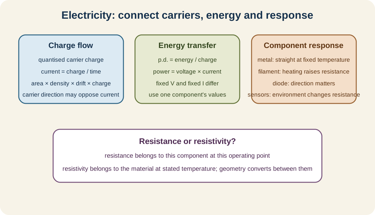
Electricity is Topic 9 of the Cambridge International AS and A Level Physics 9702 AS Level syllabus. Its official boundary covers electric current and charge carriers in section 9.1, potential difference and power in section 9.2, and resistance, resistivity and component behaviour in section 9.3.
9.1 Electric current
Flow of charge carriers
Electric current is a flow of charge carriers. In a metal, mobile electrons carry charge. In electrolytes, positive and negative ions can carry charge. In semiconductors, electrons and holes can contribute.
Conventional current direction is the direction positive charge would flow. In a metal it is opposite to electron drift.
Current does not mean that electrons travel through the circuit at the speed of light. Their average drift is slow, while the electric field establishing circuit response propagates through the circuit much faster.
Charge is conserved at junctions. Charge carriers are not used up by a component; energy is transferred from them and the field to other stores.
Quantised charge
Charge on an isolated object occurs in integer multiples of the elementary charge:
Q=Ne,
where N is an integer and
Check this topic from memory
Attempt the matching topic bank before reopening the notes. Use each missed idea to decide what to review next.
An electron has charge −e, while a proton has charge +e. Use magnitude when counting carriers and retain sign when direction or net charge matters.
The calculated number of carriers should be an integer in an exact microscopic count. Macroscopic charge measurements can make the integer step effectively unnoticeable.
Do not confuse charge Q with number of carriers N.
Current, charge and time
Current is rate of flow of charge:
I=ΔtΔQ.
For steady current:
Q=It.
The ampere is coulomb per second. The area under a current-time graph gives charge transferred.
If current changes, use the graph area or the appropriate average rather than multiplying one instantaneous value by the entire time.
Charge direction and conventional-current direction must be distinguished when negative carriers move.
Drift-current expression
Consider a conductor of cross-sectional area A, number density of mobile carriers n, carrier charge magnitude q and mean drift speed v.
In time Δt, carriers within length vΔt pass a cross-section. Their number is nAvΔt, so transferred charge magnitude is nAvqΔt. Therefore:
I=Anvq.
The units reduce to amperes:
m2×m−3×m⋅s−1×C=C⋅s−1.
For a given current and carrier density, a larger cross-sectional area requires a smaller drift speed.
Use number density per cubic metre and cross-sectional area normal to carrier motion.
The expression describes magnitude unless signed charge and velocity are handled consistently as vectors.
9.2 Potential difference and power
Potential difference
Potential difference across a component is energy transferred from electrical energy per unit charge passing through it:
V=QW.
One volt is one joule per coulomb.
A potential difference of 12V means 12J is transferred per coulomb through the component.
Potential difference is measured between two points. It is not a quantity that flows through a component.
Conventional current through a passive component moves from higher to lower potential, while electrons drift oppositely in a metal.
Electrical power
Power is energy transferred per unit time:
P=tW.
Using W=VQ and Q=It:
P=VI.
For a component obeying V=IR, substitution gives:
P=I2RandP=RV2.
Choose the form matching known quantities and the actual voltage or current of that component.
Energy transferred over time is E=Pt=VIt. Kilowatt-hour is an energy unit, although SI calculations usually use joules.
The power expressions involving R are algebraic consequences of V=IR for the relevant operating condition.
Interpreting power changes
At fixed resistance, P∝V2, so doubling voltage makes power four times as large.
At fixed voltage, increasing resistance lowers power because P=V2/R. At fixed current, increasing resistance raises power because P=I2R.
These are different controlled conditions. Do not claim one universal relationship between resistance and power.
For non-ohmic components, use instantaneous P=VI at the chosen operating point. Resistance can change with temperature or current.
9.3 Resistance and resistivity
Resistance
Resistance of a component at an operating point is
R=IV.
Its SI unit is ohm, Ω=V⋅A−1.
Resistance describes the ratio of potential difference to current. It need not be constant.
Conductance is the reciprocal of resistance, but it is not an explicit requirement here.
Use the potential difference across and current through the same component.
Ohm's law
Ohm's law states that current in a metallic conductor is directly proportional to potential difference across it, provided temperature and other physical conditions remain constant.
An ohmic conductor has a straight current-potential-difference characteristic through the origin at constant temperature.
The constant-temperature condition is essential. A filament can be made of metal yet be non-ohmic during operation because its temperature changes.
Ohm's law is an empirical relationship under controlled conditions, not merely the rearrangement V=IR.
Metallic conductor characteristic
With current on the vertical axis and potential difference on the horizontal axis, a metallic conductor at constant temperature gives a straight line through the origin.
The gradient of an I-against-V graph is I/V=1/R. If axes are reversed, gradient is R.
The characteristic is symmetric under reversal for an ordinary metallic resistor.
A steeper I-against-V line means lower resistance.
Filament lamp characteristic
A filament lamp's characteristic curves with decreasing gradient as magnitude of voltage and current rise.
Increasing current heats the filament. Higher temperature increases lattice vibration and electron scattering, so resistance rises.
The curve is approximately symmetric for positive and negative directions because reversing polarity does not change the heating mechanism.
At each point, resistance is V/I, not simply the inverse tangent-gradient of a curved graph.
Semiconductor diode characteristic
A diode conducts strongly in its forward direction after a characteristic turn-on region, but carries negligible current in reverse direction until breakdown conditions outside ordinary operation.
Its characteristic is strongly asymmetric. Diode resistance depends on operating point and direction.
Do not draw the forward branch as a vertical line at zero voltage or show large reverse current under normal conditions.
Identify the axes and polarity before interpreting forward bias.
Resistivity
For a uniform conductor:
R=ρAL,
where L is length, A is cross-sectional area and ρ is material resistivity.
Resistivity has SI unit Ω⋅m. It is a material property at a stated temperature, whereas resistance also depends on specimen geometry.
Longer conductors have greater resistance because carriers encounter more scattering along the path. Larger cross-sectional area gives lower resistance because more parallel conducting paths are available.
For a wire of diameter d:
A=4πd2.
Convert diameter before squaring. A percentage uncertainty in diameter contributes twice that percentage to area and resistivity when other uncertainties are treated simply.
The equation assumes uniform material, cross-section and temperature.
Light-dependent resistor
An LDR's resistance decreases as incident light intensity increases. Light releases or creates more mobile charge carriers in the semiconductor.
Its resistance-light relationship is non-linear. State the trend unless a quantitative model is supplied.
In a potential divider, the output response depends on whether the LDR is the upper or lower component. The resistance trend alone does not determine whether output voltage rises.
Negative-temperature-coefficient thermistor
For the thermistors assumed in this syllabus, resistance decreases as temperature increases.
Heating increases the number of available mobile charge carriers enough to reduce resistance, despite increased scattering.
The characteristic is non-linear. Do not apply a metallic-conductor positive temperature trend.
As with an LDR, a divider's output direction depends on thermistor position.
Worked application: linking carrier motion, geometry and power
A wire of area 1.2⋅10−6m2 carries 2.4A. With n=8.5⋅1028m−3 and q=1.60⋅10−19C, drift speed is v=I/(Anq)=1.47⋅10−4m⋅s−1. If its length is 3.0m and resistivity 1.7⋅10−8Ω⋅m, resistance is R=ρL/A=0.0425Ω. Power transferred is I2R=0.245W. The corresponding p.d. is IR=0.102V, which also gives the same power from VI. Slow drift is fully consistent with immediate circuit response and continuous energy transfer.
Common misconceptions and corrections
Calling current the flow of electrons in every material. The carriers depend on the medium.
Drawing conventional current in the electron-drift direction. They are opposite in metals.
Saying charge carriers are consumed by a resistor. Charge is conserved.
Saying electrons move around the circuit at light speed. Drift speed is much lower.
Using Q=Ne without integer carrier count. Quantisation requires whole carriers.
Ignoring electron charge sign when net charge direction matters. Distinguish sign from magnitude.
Calling current total charge. It is charge flow rate.
Using Q=It for a changing current without averaging or area. Integrate the graph.
Using conductor length instead of cross-sectional area in I=Anvq. Area is normal to flow.
Using carrier number rather than number density.n is per unit volume.
Calling potential difference energy. It is energy per charge.
Saying voltage flows. Charge flows; p.d. is between points.
Using total circuit charge in V=W/Q without the relevant transfer. Match component and charge.
Calling power energy. Power is transfer rate.
Using I2R with a current from another component. Use the component operating values.
Saying resistance always raises or lowers power. State what is held constant.
Defining resistance as opposition only. Use the measurable ratio V/I.
Saying every component has constant resistance. Non-ohmic resistance changes.
Stating Ohm's law without constant physical conditions. Temperature must be controlled.
Calling V=IR itself the full statement of Ohm's law. Proportionality and conditions matter.
Reading I-against-V gradient as resistance. It is conductance.
Drawing a filament curve with increasing gradient. Heating raises resistance.
Explaining a filament curve without temperature. Heating is the causal link.
Drawing a diode characteristic symmetrically. Its directions differ.
Showing a large normal reverse diode current. It is negligible before breakdown.
Calling resistivity a property of shape. It is a material property at stated temperature.
Giving resistivity in ohms. Use ohm metre.
Saying a thicker wire has greater resistance. Larger area lowers resistance.
Forgetting to square diameter in wire area. Use πd2/4.
Applying R=ρL/A to a non-uniform conductor without qualification. Its assumptions matter.
Saying LDR resistance rises with light. It decreases.
Saying the assumed thermistor behaves like a metal. Its resistance decreases with temperature.
Predicting sensor-divider output without component position. Analyse the divider.
Assessment guidance
Start charge-flow questions by naming the carrier and distinguishing its motion from conventional current. In drift calculations, convert area, number density and carrier charge to SI units and test the very small speed physically. For potential difference and power, identify energy per charge first and use the voltage and current of the same component. On characteristic graphs, state the axes before using gradient, describe symmetry or direction and link filament curvature explicitly to heating. State Ohm's law with constant temperature. In resistivity problems, distinguish material from geometry, use cross-sectional rather than surface area and square diameter conversions. For LDRs and thermistors, state the resistance trend first and analyse circuit position separately.
Retrieval practice
Derive I=Anvq from a carrier-filled cylinder and solve charge quantisation and current-time graph problems. Derive all three electrical power forms and compare fixed-current with fixed-voltage changes. Sketch and explain constant-temperature metal, filament and diode characteristics with named axes. Determine resistivity from wire measurements, then predict LDR and negative-temperature-coefficient thermistor resistance changes before placing each in both positions of a potential divider.