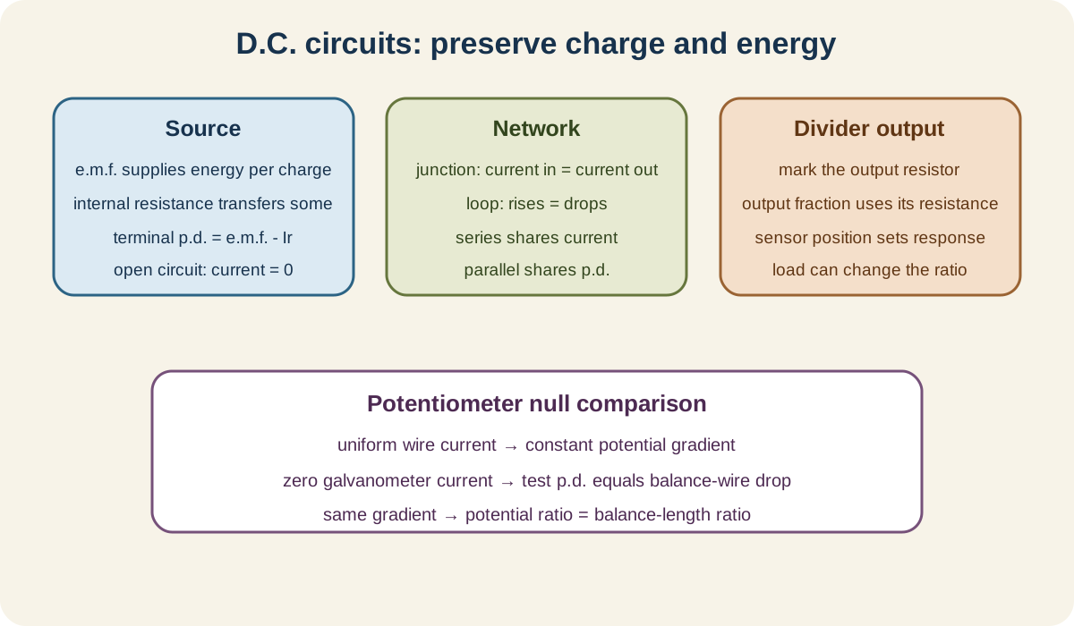
D.C. circuits is Topic 10 of the Cambridge International AS and A Level Physics 9702 AS Level syllabus. The official boundary covers practical circuit representation, e.m.f. and internal resistance in section 10.1, charge and energy conservation through Kirchhoff's laws in section 10.2, and potential-divider and null methods in section 10.3.
10.1 Practical circuits
Circuit symbols and diagrams
Use the circuit symbols specified in section 6 of the official syllabus. The required vocabulary includes sources and cells, switches, fixed and variable resistive components, lamps, diodes, meters, sensors and connection conventions.
A circuit diagram represents electrical connections, not the physical positions of apparatus. Straight wires that meet with a junction marker are connected; crossing wires without a junction are not.
Draw an ammeter in series with the branch whose current it measures. Draw a voltmeter in parallel across the component whose potential difference it measures.
An ideal ammeter has negligible resistance so it does not significantly change current. An ideal voltmeter has effectively infinite resistance so it draws negligible current.
Use the correct cell polarity and diode orientation. Label component values and currents rather than relying on drawing size.
Trace every path from the source to check that switches, meters and components are connected as intended.
Electromotive force
Electromotive force of a source is energy transferred per unit charge in driving charge around the complete circuit:
ε=QWsource.
Check this topic from memory
Attempt the matching topic bank before reopening the notes. Use each missed idea to decide what to review next.
Its unit is volt. Despite its name, e.m.f. is not a force.
The source transfers chemical or other stored energy into electrical energy. A 1.5V cell ideally transfers 1.5J per coulomb around the full circuit.
Potential difference across a component is energy transferred from electrical energy per unit charge in that component.
E.m.f. describes energy supplied per charge; p.d. describes energy transferred per charge. Both share unit volt but represent different parts of the energy account.
Internal resistance
A real source has internal resistance r. When current I flows, energy per charge Ir is transferred inside the source as internal heating.
For a source of e.m.f. ε connected to external resistance R:
ε=I(R+r).
The terminal potential difference is
V=ε−Ir=IR.
The quantity Ir is lost volts. It is not lost energy; it is energy transferred per charge internally.
With no current drawn, ideal voltmeter terminal p.d. equals e.m.f. Under load, terminal p.d. falls as current rises.
For a charging source, current direction can make terminal p.d. exceed e.m.f.; follow energy and sign conventions rather than applying the discharge formula blindly.
Source power and efficiency
Source power supplied is
Psource=εI.
Useful external power is VI=I2R, and internal heating power is I2r.
For the simple source-load circuit, useful transfer efficiency is
η=εV=R+rR.
A large external resistance gives high transfer efficiency but not necessarily maximum useful power. Efficiency and output power are different criteria.
10.2 Kirchhoff's laws
First law and charge conservation
Kirchhoff's first law states that the total current entering a junction equals the total current leaving:
∑Iin=∑Iout.
It follows from conservation of charge. Charge does not accumulate indefinitely at an ordinary steady-current junction.
Choose current directions initially. If a solved current is negative, the real direction is opposite to the assumed arrow.
Apply the law to one junction at a time and avoid counting the same branch current twice.
Second law and energy conservation
Kirchhoff's second law states that the algebraic sum of e.m.f.s and potential differences around any closed loop is zero:
∑ε=∑IR
for a loop written with consistent signs.
It follows from conservation of energy per unit charge. A charge returning to its starting potential has zero net energy change.
When traversing a source from negative to positive terminal, count an e.m.f. rise. Across a resistor in the current direction, count a potential drop.
An alternative sign convention is valid if applied consistently. Label loop direction and current arrows before writing equations.
Deriving resistors in series
Resistors in series carry the same current. Kirchhoff's second law gives:
V=V1+V2+⋯=IR1+IR2+⋯.
Since V=IRtotal:
Rtotal=R1+R2+⋯.
Series resistance exceeds every individual positive resistance because each component adds another potential drop for the same current.
Voltage divides in proportion to resistance for a series chain carrying one current.
Deriving resistors in parallel
Parallel resistors share the same potential difference. Kirchhoff's first law gives:
I=I1+I2+⋯=R1V+R2V+⋯.
Since I=V/Rtotal:
Rtotal1=R11+R21+⋯.
The total parallel resistance is smaller than the smallest branch resistance because extra branches provide more conducting paths.
For two resistors:
Rtotal=R1+R2R1R2.
Solving multi-loop circuits
Mark branch currents and source polarities. Use first-law equations at junctions and independent second-law equations around loops.
Do not create more unknown currents than necessary. A junction equation can express one branch current in terms of others before loop equations are solved.
Include internal resistance as a resistor in series with its source.
After solving, check junction charge balance, loop energy balance and whether signs make physical sense.
Power supplied by sources should equal total power transferred in resistive components for a steady idealised circuit.
10.3 Potential dividers
Divider principle
Two resistors R1 and R2 in series across input Vin carry the same current:
I=R1+R2Vin.
Output across R2 is
Vout=VinR1+R2R2.
Output is the fraction of total series resistance across which it is measured.
State clearly which resistor is the output component. If output is taken across R1, the numerator changes.
The simple formula assumes negligible output loading. A connected low-resistance device appears in parallel with the output resistor and changes the ratio.
Variable dividers
A potentiometer used as a potential divider has a sliding contact that selects a fraction of the resistance and therefore a fraction of the supply potential.
At one end, output can approach zero; at the other, it can approach the full input, under negligible load.
A variable resistor connected with two terminals controls current, while a potentiometer connected across a supply with a sliding output divides potential. The drawing determines its role.
Sensor dividers
An LDR's resistance decreases as light intensity rises. A negative-temperature-coefficient thermistor's resistance decreases as temperature rises.
If the sensor is the lower resistor and output is across it, falling sensor resistance makes output fall. If it is the upper resistor and output is across the fixed lower resistor, falling sensor resistance makes output rise.
Do not memorise one output direction. Write the divider fraction using the actual circuit.
The greatest sensitivity is often obtained when the fixed resistor is comparable to sensor resistance near the intended operating condition.
Potentiometer comparison of potential differences
A uniform resistance wire carrying steady current has a constant potential gradient:
k=LwireVwire.
Potential difference along balance length l is
V=kl.
To compare two e.m.f.s or potential differences using the same wire current:
V2V1=l2l1.
The unknown source is connected in opposition to the potential drop along the wire. Move the contact until the galvanometer shows zero.
At balance, no current flows through the test source branch, so its internal resistance causes no lost volts. This null method compares e.m.f.s without drawing current from them at the balance point.
Galvanometer in a null method
A galvanometer detects small current and its direction. A zero reading shows that the compared potential differences are equal and opposite.
Null does not mean the main potentiometer wire carries no current. It means no current flows in the detector branch.
Choose the driving source so the full wire drop exceeds the unknown e.m.f.; otherwise no balance point exists.
Use a long uniform wire and keep its current constant. Avoid heating, which changes resistance and potential gradient.
Detailed wiring execution, meter protection and uncertainty evaluation belong to the Cambridge Physics practical-skills series. The theory ownership here is the balance principle, ratios and energy reason for zero test current.
Worked application: source, divider and null evidence
A cell with ε=6.0V and r=1.0Ω drives R=5.0Ω. Current is 6.0/(5.0+1.0)=1.0A, terminal p.d. is 5.0V, and 1.0V per coulomb is transferred internally. A 2.0Ω-3.0Ω unloaded divider across the terminal gives Vout=5.0(3.0/5.0)=3.0V across the lower resistor. A potentiometer comparison with balance lengths 45.0 cm and 60.0 cm gives V1/V2=0.750 without drawing test-branch current at either null.
Common misconceptions and corrections
Treating a circuit drawing as apparatus layout. It represents electrical connections.
Connecting an ammeter in parallel. It belongs in the measured branch.
Connecting a voltmeter in series. It belongs across two points.
Calling e.m.f. a force. It is source energy per charge.
Treating e.m.f. and p.d. as identical energy roles. One supplies; the other transfers.
Saying internal resistance lies outside the source. It models transfer inside it.
Calling Ir lost energy. It is internal p.d., or energy per charge.
Setting terminal p.d. equal to e.m.f. while current flows through internal resistance. Subtract lost volts.
Using V=ε+Ir for an ordinary discharging cell. Terminal p.d. is lower.
Saying high efficiency guarantees maximum load power. They optimise differently.
Calling Kirchhoff's first law energy conservation. It follows from charge conservation.
Calling Kirchhoff's second law charge conservation. It follows from energy conservation.
Ignoring assumed current direction. A negative result reverses it.
Adding unsigned voltage drops around a loop. Use a consistent traversal convention.
Adding parallel resistances directly. Add their reciprocals.
Adding reciprocal series resistances. Series values add directly.
Accepting a parallel total above the smallest branch. Recheck the calculation.
Saying current is equal in parallel branches. Potential difference is equal.
Saying voltage is equal across series components. Current is equal.
Omitting internal resistance from a loop. It contributes a drop.
Writing dependent loop equations as if independent. Choose sufficient independent loops.
Skipping power balance. It is a useful final energy check.
Using the wrong divider resistor in the numerator. Use the output component.
Saying a divider always halves voltage. Only equal resistances do.
Ignoring output loading. The load changes effective lower resistance.
Predicting LDR output from its trend alone. Component position matters.
Predicting thermistor output from its trend alone. Write the actual divider fraction.
Calling every three-terminal variable resistor a divider regardless of wiring. Connection sets its function.
Saying potentiometer balance means no main-wire current. Only detector-branch current is zero.
Using an ordinary voltmeter as the null detector. A galvanometer detects balance current.
Claiming the test cell supplies current at balance. It supplies none to that branch.
Comparing balance lengths with different wire currents. The potential gradient must remain the same.
Choosing a wire drop below the unknown e.m.f. No balance point can occur.
Including spectrometer-like or unrelated apparatus detail. Keep the method circuit-specific.
Assessment guidance
Begin by redrawing a clear circuit with source polarity, junctions, meters and assumed current arrows. Separate e.m.f., terminal p.d. and internal lost volts using energy per charge. At each junction apply charge conservation; around each independent loop use signed energy changes. Derive series and parallel combinations from those laws when requested rather than quoting them. In divider questions, mark the output terminals and include loading only when present. For LDRs and thermistors, state the resistance trend, identify upper or lower position and then use the divider fraction. In potentiometer answers, explain uniform potential gradient, zero galvanometer current and why null removes internal-resistance loading of the test source.
Retrieval practice
Draw and interpret circuits using every official symbol, then calculate e.m.f., terminal p.d., internal power and load power. Derive both resistor-combination formulas from Kirchhoff's laws and solve a two-loop circuit with signed currents. Analyse loaded and unloaded potential dividers with LDRs and thermistors in both positions. Finally, derive the potentiometer length ratio, state the balance conditions and explain why the null method compares e.m.f.s without drawing current.