Cambridge International AS and A Level Physics 19: Capacitance
Cambridge International AS and A Level Physics 19: Capacitance
Study guide/
Cambridge Physics 9702 A Level notes on capacitance, isolated and parallel-plate capacitors, series and parallel combinations, stored energy and resistor discharge.
Capacitance is Topic 19 of the Cambridge International AS and A Level Physics 9702 additional A Level content. Sections 19.1 to 19.3 connect charge stored per potential, capacitor combinations, energy under a potential-charge graph and exponential discharge through resistance. Dielectrics are not an explicit outcome in this syllabus boundary.
19.1 Capacitors and capacitance
Capacitance definition
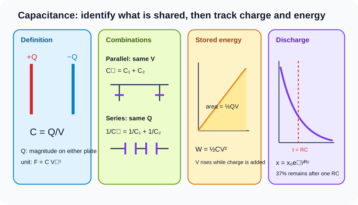
Capacitance C is charge stored per unit potential. For an isolated spherical conductor, Q is its charge and V is its potential relative to the chosen zero. For a parallel-plate capacitor, Q is the magnitude of charge on either plate and V is the potential difference between the plates.
C=VQ.
The SI unit is the farad, equal to coulomb per volt. One farad is large, so microfarad, nanofarad and picofarad values are common.
Capacitance characterises conductor geometry and surroundings under the model conditions. The equation does not mean that changing Q or V changes C for an ideal fixed capacitor; Q and V change proportionally.
Check this topic from memory
Attempt the matching topic bank before reopening the notes. Use each missed idea to decide what to review next.
A capacitor stores equal and opposite plate charges. Its net charge can be zero even while the magnitude Q used in the capacitance equation is non-zero.
For an isolated conductor, adding charge raises its potential. For a two-plate capacitor, transferring charge between plates establishes a potential difference and electric field.
Parallel combination
Capacitors in parallel share the same potential difference V. Total charge supplied is the sum of branch charges:
Q=Q1+Q2+⋯.
Using Q = CV for every branch:
CtotalV=C1V+C2V+⋯.
Cancel the common potential difference:
Ctotal=C1+C2+⋯.
Parallel connection provides more charge storage per volt, so total capacitance exceeds any individual capacitance.
Do not copy the parallel-resistor reciprocal rule. Derive from shared voltage and charge addition.
Series combination
Capacitors in series acquire equal charge magnitude Q on each capacitor in an initially uncharged chain. The total potential difference is the sum:
V=V1+V2+⋯.
Using V = Q/C:
CtotalQ=C1Q+C2Q+⋯.
Cancel common Q:
Ctotal1=C11+C21+⋯.
Series total capacitance is smaller than the smallest component. For two capacitors:
Ctotal=C1+C2C1C2.
In series, the smaller capacitance has the larger potential difference because V = Q/C and charge magnitude is shared.
Equal charge in series does not mean equal potential unless capacitances are equal.
Combination strategy
Identify nodes before applying a rule. Components are parallel only if both terminals connect to the same two nodes. They are series only if their shared junction has no additional branch affecting the equal-charge argument.
Reduce a mixed network in stages. After finding total capacitance, use total Q = C_total V, then work back through shared voltage or shared charge conditions.
Check bounds: a parallel equivalent must exceed its largest branch value; a series equivalent must be below its smallest component value.
19.2 Energy stored in a capacitor
Potential-charge graph
Charging a capacitor requires increasing work because its potential rises with charge. For a fixed capacitance:
V=CQ.
On a graph of potential V against charge Q, the gradient is 1/C. Energy transferred to the capacitor is the area under the V against Q graph:
W=∫0QV,dQ.
For a linear capacitor, the graph is a triangle with base Q and height V:
W=21QV.
Substituting Q = CV gives
W=21CV2.
The factor one half appears because potential rises from zero to final V; not every transferred coulomb crosses the final potential.
An equivalent form, obtained from V = Q/C, is Q squared divided by 2C. Use the form matching known quantities, although the official recall boundary explicitly names one half QV and one half CV squared.
Stored energy is electric potential energy associated with the charged system and its field. A capacitor does not create energy; charging transfers energy from a source.
At fixed capacitance, doubling V makes stored energy four times as large. At fixed V, doubling C doubles stored energy. State what is held constant before using proportionality.
Energy during network changes
For capacitors still connected to an ideal source, voltage may remain fixed while charge changes. For an isolated charged capacitor, charge may remain fixed while geometry or connections change. These different constraints produce different energy trends.
The syllabus formulas support calculations, but do not assume fixed Q and fixed V simultaneously during a physical change unless the question justifies it.
When a charged capacitor discharges through a resistor, stored electric energy transfers mainly to internal energy in the resistor.
19.3 Discharging a capacitor
Exponential quantities
For a capacitor discharging through resistance R, charge, potential difference and current magnitude all decrease exponentially:
x=x0e−t/(RC),
where x may be Q, V or current magnitude I, and x0 is the corresponding initial value.
The time constant is
τ=RC.
Resistance in ohms multiplied by capacitance in farads gives seconds.
At one time constant:
x0x=e−1≈0.368.
So about 37 per cent remains, not 50 per cent. About 63 per cent of the initial amount has changed.
After each additional time constant, the remaining fraction is multiplied by e to the minus one again. The curve approaches zero asymptotically rather than reaching zero at a finite time in the ideal model.
Why the rate falls
During discharge, V = Q/C. Circuit current magnitude is V/R, so
I=RCQ.
As Q falls, V and current magnitude fall. The discharge rate is therefore largest initially and becomes progressively smaller.
With a chosen current direction, capacitor current may be negative relative to the charging direction. A current-time graph can lie below the axis while its magnitude decays toward zero. Read the stated sign convention rather than assuming every exponential is positive.
The initial current magnitude is
I0=RV0.
Larger R reduces initial current and increases time constant. Larger C stores more charge per volt and also increases time constant.
Reading discharge graphs
Charge and potential graphs have identical fractional shapes because V = Q/C for fixed C. Current magnitude has the same exponential factor.
Initial value is the vertical intercept. The tangent at any point has a characteristic relationship to the remaining value. For x against t:
dtdx=−RCx.
The initial tangent meets the time axis at one time constant for an ideal exponential decay. This graphical construction can estimate RC without assuming a half-life.
Taking natural logarithms gives
lnx=lnx0−RCt.
A graph of ln x against t is straight with gradient minus 1/RC. Logarithms require a positive magnitude, so use current magnitude if signed current is negative.
Energy decay
Since stored energy is one half C V squared and V decays as e to the minus t over RC:
W=W0e−2t/(RC).
Energy therefore has a different exponential factor from voltage, charge and current. It falls to e to the minus two of its initial value after one RC.
This energy result is a consequence of the official formulas, useful for avoiding the misconception that every capacitor quantity shares exactly the same time constant expression in its unsquared form.
Theory and practical ownership
This theory note covers capacitance definitions, network derivations, graph-area energy and exponential discharge analysis.
Practical work covers circuit switching, voltmeter or data-logger loading, capacitor tolerance, resistor measurement, safe discharge, timing, graph linearisation, uncertainty and evaluation. A theory graph assumes ideal components; the practical hub investigates departures.
Worked application: series charging and discharge
Capacitors 6.0uF and 3.0uF in series across 12V have equivalent capacitance 2.0uF and shared charge magnitude Q=CtotalV=24uC. Their potential differences are 4.0 V and 8.0 V respectively. If the equivalent capacitor discharges through 2.5Mohm, then RC=5.0s. After 10 s, voltage is 12e−2=1.62V. Initial stored energy is CV2/2=144uJ, while after 10 s it is multiplied by e to the minus four, not e to the minus two.
Common misconceptions and corrections
Defining capacitance as charge alone. It is charge per unit potential.
Using total two-plate net charge as Q. Use the magnitude on either plate.
Saying capacitance changes whenever Q changes. For a fixed ideal capacitor, Q and V change proportionally.
Writing farad as volt per coulomb. It is coulomb per volt.
Treating microfarads as farads without conversion. Apply the power of ten.
Using the series rule for parallel capacitors. Parallel shares voltage and adds charge.
Using the parallel rule for series capacitors. Series shares charge magnitude and adds voltage.
Saying series capacitors always share voltage equally. Only equal capacitances do.
Saying parallel capacitors share charge equally. Charge is proportional to capacitance.
Accepting a series equivalent larger than a component. It must be smaller than the smallest.
Accepting a parallel equivalent smaller than a component. It must exceed the largest branch value.
Calling components parallel because they look side by side. Check both circuit nodes.
Calling a branched junction a simple series connection. Equal-charge reasoning may fail.
Using resistor combination rules by memory. Derive from Q = CV.
Calling QV the stored energy. The linear charging graph gives one half QV.
Saying the potential is final V throughout charging. It rises from zero.
Reading graph gradient as capacitance on a V-Q graph. Gradient is 1/C.
Reading area under a Q-V graph without checking axes. Energy is integral of V with respect to Q.
Saying doubling V doubles energy at fixed C. It quadruples energy.
Saying a capacitor produces stored energy. A source transfers it during charging.
Assuming Q and V both stay fixed during a network change. Identify the physical constraint.
Using x = x0 e positive t over RC for discharge. The exponent is negative.
Saying one time constant leaves half. It leaves about 37 per cent.
Saying the capacitor reaches exactly zero after five RC. It approaches zero asymptotically.
Using tau equal to R divided by C. Time constant is RC.
Using microfarads directly with ohms. Convert to farads for seconds.
Saying discharge current remains constant. Falling voltage reduces current.
Ignoring signed current direction. Its graph may be negative while magnitude decays.
Giving charge, voltage and current different RC factors. Their magnitudes share e to the minus t over RC.
Giving stored energy the same exponential factor as voltage. Squaring voltage produces e to the minus 2t over RC.
Using ln of negative current. Linearise current magnitude.
Treating measurement loading as part of the ideal equation. It is practical non-ideality.
Assessment guidance
Define Q and V for the stated capacitor type before using C = Q/V. Derive combinations from shared voltage or shared charge rather than importing resistor rules, and test the equivalent against network bounds. On a potential-charge graph, identify axes before using area and explain the one-half factor. For discharge, convert R and C to SI units, calculate RC, then form the dimensionless exponent. State whether current is signed or a magnitude. At one RC expect 0.368 of Q, V or current magnitude. Use squared voltage for energy and therefore double the exponential decay constant in the exponent.
Retrieval practice
Derive series and parallel capacitance from Q = CV and solve a mixed network by working back to branch values. Sketch and interpret a V-Q graph, then derive both official energy forms. From one RC circuit, calculate initial current, remaining Q, V and current after several times, construct a logarithmic graph and compare voltage decay with energy decay.