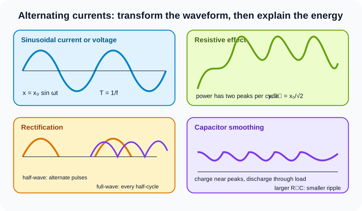
Alternating currents is Topic 21 of the Cambridge International AS and A Level Physics 9702 additional A Level content. Sections 21.1 and 21.2 connect sinusoidal timing and r.m.s. meaning to resistive power, diode rectification and capacitor smoothing. Transformers are not an explicit outcome in this Topic 21 boundary.
21.1 Characteristics of alternating currents
Alternating quantities
An alternating current changes direction periodically. An alternating voltage changes polarity periodically. A sinusoidal alternating quantity x can be represented by
x=x0sinωt,
where x0 is the peak magnitude and omega is angular frequency.
For current, x may be I; for voltage, x may be V. A negative value shows reversal relative to the chosen positive direction or polarity. It does not mean the magnitude is physically impossible.
Period T is time for one complete cycle. Frequency f is cycles per second:
f=T1.
Check this topic from memory
Attempt the matching topic bank before reopening the notes. Use each missed idea to decide what to review next.
Peak value is maximum magnitude from zero. Peak-to-peak value is twice the peak for a symmetric sinusoid. Do not substitute peak-to-peak into an equation that asks for x0.
The phase omega t is measured in radians. At a quarter period the phase advances by pi over two; at half a period it advances by pi and the sign reverses.
Instantaneous power in a resistor
For a pure resistance R with sinusoidal current
I=I0sinωt,
instantaneous power is
P=I2R=I02Rsin2ωt.
Power remains non-negative because current and voltage reverse together. Energy is transferred to internal energy during both half-cycles.
Maximum power is
P0=I02R.
The mean value of sine squared over one cycle is one half, so
Pmean=21P0.
Equivalently, for voltage across a resistor, maximum power is V0 squared divided by R and mean power is half that value.
Power oscillates at twice the current frequency because squaring removes sign and produces two peaks per current cycle.
Root-mean-square values
The r.m.s. current is the direct current that would produce the same mean power in a resistor as the alternating current.
Since mean alternating power is I0 squared R divided by two and direct power is I_r.m.s. squared R:
Ir.m.s.=2I0.
Similarly,
Vr.m.s.=2V0.
These peak-to-r.m.s. factors apply to a sinusoidal waveform. Do not use them automatically for rectified, square or irregular waveforms.
For a resistive load, current and voltage are in phase and
Pmean=Ir.m.s.Vr.m.s.=Ir.m.s.2R=RVr.m.s.2.
R.m.s. is not the arithmetic mean of a symmetric alternating current, which is zero over a full cycle. The operation is square, mean, then root.
Meters and supply ratings commonly use r.m.s. values because they express equivalent resistive heating effect. Always identify whether a stated value is peak, peak-to-peak or r.m.s.
Reading sinusoidal graphs
Find period from equal-phase points such as consecutive positive peaks, not from adjacent zero crossings unless the half-cycle factor is applied.
Read peak magnitude from the zero axis to a maximum. If a graph begins away from zero, a phase shift may be present even though the amplitude and period are unchanged.
For x = x0 sin omega t, initial x is zero and initially increases. A cosine-shaped trace or shifted sine requires a phase term; do not force every graph into the zero-phase form without checking its starting condition.
21.2 Rectification and smoothing
Diode action
An ideal diode conducts readily in its forward direction and blocks current in the reverse direction. Rectification uses this one-way behaviour to turn alternating input into a unidirectional output.
Rectified output is not automatically steady direct current. Its direction is one-way, but its magnitude can pulse.
Half-wave rectification
A single series diode provides half-wave rectification. During the input half-cycle that forward-biases the diode, current passes through the load. During the opposite half-cycle, the diode is reverse-biased and ideal load current is zero.
The output graph contains pulses from alternate input half-cycles separated by zero intervals. Its pulse repetition frequency equals the input frequency.
Reversing the diode reverses which half-cycles appear and the output polarity across the load.
Half-wave rectification discards one half of the input cycles, giving wider gaps and larger potential ripple for the same smoothing components than full-wave rectification.
Full-wave bridge rectification
A bridge rectifier uses four diodes. On one input half-cycle, one diagonal pair conducts. On the next half-cycle, the other diagonal pair conducts.
Although source polarity reverses, current through the load has the same direction on both half-cycles. The negative input half is effectively turned upward in an output-time graph.
Full-wave output has a pulse every half-cycle, so ripple frequency is twice the input frequency. There are no alternate zero half-cycles in the ideal unsmoothed waveform, although instantaneous output reaches zero at input crossings.
Do not claim all four diodes conduct simultaneously. Two conduct in each half-cycle for the usual bridge path.
To determine load polarity, trace conventional current from the instantaneously positive source terminal through a forward diode, the load and a second forward diode to the negative source terminal. Repeat after source reversal.
Capacitor smoothing
A capacitor connected across the load charges when rectified input rises above capacitor voltage. Near a peak, diode conduction replenishes charge.
As input falls, the diode becomes reverse-biased. The capacitor then discharges through the load, supplying current and slowing the fall of output voltage until the next charging peak.
The smoothed output is a direct level with ripple, not a perfectly horizontal line. Ripple is the repeated fall and recharge in capacitor voltage.
The discharge time constant is approximately load resistance times capacitance:
τ=RloadC.
Larger capacitance stores more charge for a given voltage and discharges more slowly, reducing ripple.
Larger load resistance draws less current and increases the time constant, also reducing ripple. A smaller load resistance represents a heavier load, gives faster discharge and increases ripple.
Full-wave rectification provides a shorter time between charging peaks than half-wave rectification at the same input frequency, so it generally produces less ripple with the same C and load R.
Increasing C or R_load does not raise every point of the waveform without limit. It changes discharge rate and practical current demand; real diode drops, source resistance and capacitor ratings can matter, but detailed component design is outside this boundary.
Sketching output waveforms
For half-wave output, retain one sign of the sine wave and replace the other half-cycle with zero.
For full-wave output, reflect the negative half-cycles above the time axis.
For smoothed output, begin near each rectified peak, then draw a gradual curved fall until rapid recharge near the next peak. A larger time constant gives a shallower fall and smaller peak-to-trough ripple.
Do not draw smoothing as averaging through both positive and negative values. The diode network first establishes unidirectional pulses; the capacitor then bridges the gaps.
Energy and current interpretation
The capacitor stores energy while charging and transfers energy to the load while discharging. Diode current occurs mainly during shorter recharge intervals, while load current continues between peaks.
The capacitor does not generate energy and does not prevent all voltage variation. It shifts energy transfer in time.
Theory and practical ownership
This theory note covers sinusoidal equations, peak and r.m.s. meaning, resistive mean power, ideal diode paths, waveform construction and qualitative smoothing trends.
Practical work covers oscilloscope scaling, circuit construction, diode orientation, component ratings, ripple measurement, capacitor polarity, load changes, uncertainty and electrical safety. The theory and practical hubs remain separate even when measured waveforms test the models.
Worked application: rms power and smoothing choice
A sinusoidal supply has peak voltage 24V across a 12ohm resistor. Its r.m.s. voltage is 24/2=17.0V, so mean power is Vr.m.s.2/R=24W, half the maximum 48W. After full-wave rectification, a 1000uF capacitor across a 120ohm load has time constant 0.12s. Increasing capacitance or load resistance reduces ripple because discharge is slower. Full-wave recharge occurs every half-cycle, so its gap is shorter than for half-wave rectification.
Common misconceptions and corrections
Saying alternating current only changes magnitude. It reverses direction.
Treating a negative current as impossible. It indicates reverse chosen direction.
Using adjacent zero crossings as one period. They are half a period apart for a sine wave.
Calling peak-to-peak value the amplitude. Peak-to-peak is twice peak.
Using omega equal to one over T. It equals 2 pi over T.
Using degrees in omega t without conversion. Phase is in radians.
Saying resistor power is negative on negative current half-cycles. I squared R remains positive.
Saying power has the same frequency as current. It has two peaks per current cycle.
Calling mean power equal to maximum power. For a sinusoid it is one half maximum.
Defining r.m.s. as average current. It is the square-mean-root effective value.
Saying symmetric alternating current has non-zero arithmetic mean. Its full-cycle mean is zero.
Multiplying peak by square root two to find r.m.s. Divide peak by square root two.
Using the sine r.m.s. factor for every waveform. It is waveform dependent.
Using peak voltage with r.m.s. current in a power product. Use consistent effective quantities.
Assuming every sinusoid starts at zero and rises. Check phase.
Saying a diode conducts equally in both directions. Rectification depends on one-way conduction.
Calling rectified output constant direct current. It is unidirectional but pulsating.
Drawing both half-cycles for a single-diode half-wave circuit. One is blocked.
Saying half-wave pulse frequency doubles. It equals input frequency.
Saying bridge output reverses through the load. Both diode pairs preserve load direction.
Saying all four bridge diodes conduct at once. One pair conducts per half-cycle.
Leaving negative full-wave lobes below the axis. Reflect them to the output polarity.
Saying full-wave ripple frequency equals input frequency. It is twice input frequency.
Putting a smoothing capacitor in series with the load. It is across the load.
Saying the capacitor charges continuously. It replenishes near rectified peaks.
Saying the capacitor discharges through the source. In the simple model it supplies the load while diodes block.
Drawing perfectly flat smoothing. Real output retains ripple.
Saying larger capacitance increases ripple. It slows discharge and reduces ripple.
Saying larger load resistance increases ripple. It reduces load current and ripple.
Calling smaller load resistance a lighter load. It draws more current.
Saying half-wave smooths better with identical components. Its recharge gaps are longer.
Saying a capacitor creates load energy. It stores and releases supplied energy.
Assessment guidance
Label period, frequency, peak and r.m.s. values before substituting. Use radians in the sinusoidal phase and distinguish peak from peak-to-peak. For a resistor, derive mean power from the squared sinusoid or use matching r.m.s. values. In rectifier questions, trace forward-biased diode paths for each half-cycle and then sketch the load waveform. Apply smoothing only after rectification. Explain ripple through charge near peaks and discharge through the load, then compare capacitance, load resistance and half-wave versus full-wave recharge intervals without claiming perfectly constant output.
Retrieval practice
Convert among T, f and omega and annotate a sine wave with peak, peak-to-peak and r.m.s. values. Derive the half-maximum mean power result. Sketch half-wave and full-wave outputs from one input trace, identify conducting bridge pairs, then add smoothing curves for larger and smaller RC values and explain every change.