Cambridge International AS and A Level Physics Practical 2: Mechanics and Materials Experiments
Cambridge International AS and A Level Physics Practical 2: Mechanics and Materials Experiments
Study guide/
Cambridge Physics 9702 practical notes on motion timing, force and moment measurements, springs, stress-strain methods and Young modulus investigations.
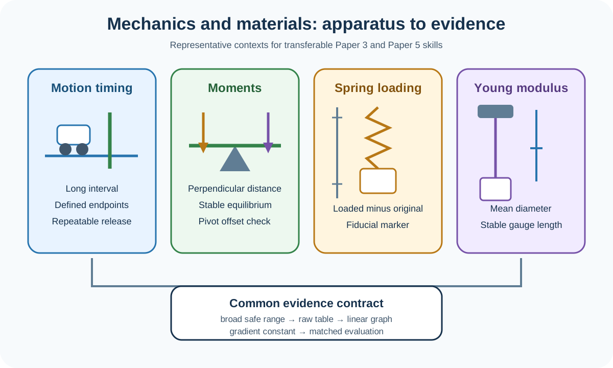
Mechanics and materials experiments provide representative contexts for the transferable skills assessed in Cambridge International AS and A Level Physics 9702 Papers 3 and 5. The syllabus does not prescribe a fixed catalogue of practicals. Instead, candidates must set up unfamiliar apparatus, collect a useful range of accurate data, process a graph, draw a bounded conclusion and evaluate the actual method.
Official practical boundary
Paper 3 can present two experiments in different areas of physics without requiring prior theory knowledge. The instructions and supplied information control the task. Candidates must collect an appropriate quantity and range of data, repeat readings where suitable, record measurements consistently, plot and interpret a trend, and evaluate a deliberately imperfect method in Question 2.
Paper 5 can ask for a workable plan in an unfamiliar context. The response must identify variables, explain how quantities are changed and measured, control relevant conditions, show a labelled apparatus arrangement, state how the data produce a conclusion and address realistic safety risks.
The mechanics and materials methods below are reusable patterns, not predictions of named examination experiments.
Time motion over a useful interval
For average speed, measure a clearly defined distance and the corresponding travel time. Mark both endpoints, keep the path geometry fixed and choose a distance long enough that timing resolution is a small fraction of the interval. A vague start or finish point creates uncertainty even when the stopwatch displays many digits.
For acceleration, use successive displacement-time measurements, light gates or a motion sensor as allowed by the apparatus. A light gate can determine an interrupt time; with a card of measured length, speed follows from card length divided by interrupt time. Two gates can compare speeds at known positions. State which measured length belongs in the calculation.
Release an object without an unintended push. A mechanical release, electromagnet or consistent support removal may reduce variation. Align the track so the intended direction of motion is controlled. If friction or air resistance matters, identify its effect on the measured relationship rather than merely writing that friction exists.
Repeat time measurements and use a mean. For periodic motion, time several complete cycles from one defined phase point and divide by the number of cycles. More cycles increase total time, but too many can allow amplitude or conditions to change, so justify the chosen compromise.
Measure forces and moments
Check that a newton meter reads zero before loading and keep the force along its calibrated axis. Avoid reading while the pointer oscillates. If a hanging mass supplies force, use the stated gravitational field strength and include the mass of any hanger when it contributes.
Check this topic from memory
Attempt the matching topic bank before reopening the notes. Use each missed idea to decide what to review next.
For moments, measure the perpendicular distance from pivot to the force's line of action. This is not automatically the distance to the object's centre or the length along a tilted ruler. Keep the system in stable equilibrium before reading and reduce pivot friction where the method permits.
A balance experiment can test a relationship of the form
F1d1=F2d2.
Vary one independent quantity over a broad safe range, control the remaining force or distance, and use a graph that produces the required constant. Reversing the beam or repeating on both sides can reveal a zero-position or centre-of-mass offset.
Do not label a discrepancy as human error. Name the measured quantity affected, the mechanism and its likely direction or random character. Examples include an uncertain pivot position, a force not exactly perpendicular, scale parallax or oscillation before equilibrium.
Investigate a spring or elastic specimen
Measure original length before loading, then calculate extension as loaded length minus original length. A results table should retain raw loaded length as well as calculated extension. Measuring only extension by moving a ruler between readings weakens traceability.
Add loads in controlled increments and wait for oscillations to settle. Keep the ruler close and parallel to the motion, and use a fiducial marker to sharpen the endpoint. Load and unload if the task concerns elastic recovery, but keep the two sequences distinguished.
For a spring in its proportional region,
F=kx.
A graph of force against extension has gradient k. A graph of extension against force has gradient 1/k. State the axis choice before interpreting the gradient. Do not force the best-fit line through the origin unless the data and model justify it.
Remain within apparatus and safety limits. A stretched spring or wire can recoil, and falling masses can injure feet or damage the bench. Use a tray or padding below the load, keep faces away from the line of recoil and do not exceed the instructed load.
Determine Young modulus
Young modulus requires tensile stress divided by tensile strain in the linear elastic region:
E=ΔL/LF/A=AΔLFL.
Measure original gauge length L between the points whose separation changes. Measure wire diameter with a micrometer at several positions and orientations, check zero, find a mean and calculate A=πd2/4. Diameter uncertainty matters strongly because area depends on diameter squared.
Clamp the wire securely and place a fiducial marker near a fixed scale. A long original length produces a larger extension for the same strain, improving fractional resolution, but the setup must remain stable. Use small load increments within the elastic range and allow the wire to settle before reading.
Possible linear graphs include F against ΔL, whose gradient is EA/L, or stress against strain, whose gradient is E. Label derived columns and axes with units. Use a large gradient triangle and derive the unit from the plotted quantities.
If the support or clamp moves, the measured displacement is not solely wire extension. A reference wire or marker fixed to the support can help separate apparatus movement from specimen extension. Simply using a more precise ruler does not correct movement of the reference point.
Design the data range and graph
Collect enough distinct values to establish a trend rather than only confirming two endpoints. Spread them across the largest safe and useful range allowed by the apparatus. A broad range strengthens a gradient because reading uncertainty becomes smaller relative to total change.
Choose the graph from the relationship being tested. If the supplied model is y=mx+c, identify y, x, gradient and intercept explicitly. If a nonlinear relationship is supplied, calculate the derived quantity needed to linearise it rather than choosing axes by habit.
Plot all points accurately, identify rather than silently delete an anomaly, and draw a line or curve that represents the overall trend. A line of best fit should balance scatter along its length. Read gradient points from the line, well separated, and do not use a false origin as if it were zero.
Evaluate the actual experiment
A limitation earns value when it identifies a specific measurement and mechanism. "It is difficult to measure extension because the marker is broad and oscillates" is actionable. "Measurements are inaccurate" is not.
Match the improvement to the limitation. A thin fiducial marker and set square address an uncertain length endpoint. A light gate addresses manual timing reaction. A rigid support or reference marker addresses clamp movement. Repeats and a mean address random variation but not a constant zero offset.
An improvement must be realistic in a school laboratory and should modify the given experiment, not replace it with a different investigation. Explain how the new arrangement changes the affected measurement.
Worked application: Young modulus from a force-extension graph
A 1.50,m wire has mean diameter 0.40,mm. A best-fit graph of force F against extension ΔL has gradient 4.2×10⁴,N⋅m−1. The cross-sectional area is A=π(0.40×10⁻³)2/4=1.26×10−7,m2. Since the gradient equals EA/L, E=(4.2×10⁴)(1.50)/(1.26×10−7)≈5.0×1011,Pa. Before accepting the value, check whether diameter was corrected for micrometer zero error, whether the gradient triangle spans more than half the line, and whether clamp movement inflated extension. Repeated diameter orientations address non-uniform wire thickness; repeated force-extension runs test scatter but do not remove a moving support bias.
Common misconceptions and corrections
Treating these examples as a prescribed Cambridge practical list. The papers assess transferable experimental skills in varied contexts.
Timing a very short interval once. Increase the measured interval and repeat where appropriate.
Using display digits as proof of timing accuracy. The start and finish definitions also matter.
Giving an object a push at release. Use a repeatable release that does not add uncontrolled motion.
Calling every discrepancy friction. Identify the interaction and its effect on the measured relationship.
Measuring moment distance along a ruler. Use perpendicular distance to the force line.
Reading a newton meter before it settles. Wait for a stable pointer or define a repeatable method.
Omitting the hanger mass. Include every mass that supplies the force when required.
Calling loaded length extension. Subtract the original length.
Recording only calculated extension. Preserve the raw length readings too.
Assuming every spring graph passes through zero. Let evidence and the stated model determine the intercept.
Taking k from extension against force without inversion. That gradient is 1/k.
Loading beyond the proportional region while applying Hooke's law. Restrict the model to its supported range.
Using one wire-diameter reading. Sample positions and orientations because area depends on diameter squared.
Using the coil diameter instead of wire diameter. Young modulus area belongs to the tensile specimen.
Measuring the wrong original length. Use the gauge length between the points that separate.
Calling support movement wire extension. Use a stable reference or compensating arrangement.
Choosing graph axes before rearranging the model. Identify the linear form first.
Calculating gradient from raw observations. Use points on the fitted line.
Choosing two close gradient points. Span more than half the line.
Deleting an anomalous point silently. Identify it and justify how the trend is drawn.
Writing "use better equipment" as an improvement. Name the apparatus and the measurement it improves.
Using repeats to correct a fixed zero error. Check and correct the offset separately.
Ignoring falling-load or recoil risk. State a specific precaution matched to the hazard.
Assessment guidance
Begin by naming independent, dependent and controlled variables, then describe exactly how each measured quantity is obtained. Choose a broad safe range and meaningful repeats. Preserve raw readings before calculating extension, speed, moment, stress or strain. Rearrange the supplied model to identify graph axes, gradient and intercept, then use a large triangle and attach the derived unit. Evaluate the apparatus actually used: name the affected measurement, explain the physical cause and give a realistic matched modification. For elastic setups, include falling-mass and recoil precautions rather than a generic instruction to be careful.
Retrieval practice
Plan one motion-timing and one Young modulus investigation. For each, define variables, apparatus, range, repeats and controls; construct the raw and derived table headings; choose a linear graph and derive its gradient meaning. Then identify one random and one systematic limitation, match each to a workable improvement and state a specific safety precaution.
Theory and practical ownership
The theory notes explain kinematics, moments, Hooke's law, stress, strain and Young modulus relationships. This practical note covers how representative mechanics and materials apparatus generate measurements, graphs, uncertainty evidence and bounded conclusions. Practical 1 retains the general uncertainty rules; Practical 6 retains full cross-context data analysis and evaluation.
Cambridge International, AS and A Level Physics 9702 syllabus for examinations in 2025, 2026 and 2027, Practical assessment expectations for Paper 3 Advanced Practical Skills and Paper 5 Planning, Analysis and Evaluation. Mechanics and materials are representative application contexts; Cambridge does not prescribe this note as a fixed experiment list.