

IGCSE Physics Practical Skills 9: Resistance and Current-Voltage Characteristics
Cambridge IGCSE Physics practical notes on resistance, current-voltage graphs, lamps, diodes, thermistors, LDRs, meter placement, heating, and evaluation.
Q: What does IGCSE Physics Practical Skills 9: Resistance and Current-Voltage Characteristics cover?
A: It gives a complete Paper 5 and Paper 6 preparation route for the named skill, including apparatus, variables, data, safety, and evaluation.
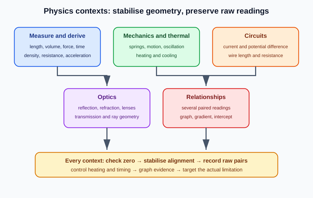
Aim
Measure how current depends on potential difference for a component or how resistance changes with a physical condition.
Apparatus and setup
- low-voltage d.c. supply, switch, and variable resistor
- ammeter in series and voltmeter in parallel
- test component such as a resistor, lamp, diode, thermistor, or LDR
- connecting leads and an appropriate sensor condition setup
Draw the apparatus as a working scientific diagram: use straight lines, label the parts that affect the method, and show where measurements are taken. Do not add decorative detail.
Method
- Draw the circuit and confirm meter positions and polarities before connection.
- Select safe meter ranges and set the variable resistor to limit current.
- Close the switch briefly, adjust the potential difference, and record paired current and voltage readings.
- Open the switch between readings when heating would change the component.
- Reverse polarity only when the question requires negative current-voltage data and the component permits it.
- Plot current against voltage or calculate resistance as directed, using a best-fit curve when the relationship is non-linear.
Variables
- Independent variable: potential difference, temperature, or light level.
- Dependent variable: current or calculated resistance.
- Controls: component, temperature unless deliberately varied, light geometry, supply, and reading delay.
A control variable is not just something kept the same. State how it is kept the same so another student could repeat the comparison.
Recording and processing results
Record each current-voltage pair with meter precision. Include both signs when polarity is reversed. Do not force a straight best-fit line through non-ohmic data.
Use one table for raw readings and calculated values when the relationship is simple. Put each unit in the heading, not in every cell. Preserve the instrument precision in raw data and round calculated values only at the end.
Check this topic from memory
Attempt the matching topic bank before reopening the notes. Use each missed idea to decide what to review next.
Start the topic quiz