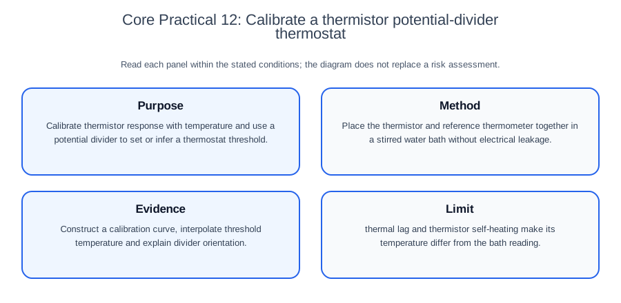
This practice outline calibrates a thermistor divider and relates its output to a temperature threshold. It supports development of a locally approved method and electrical/thermal risk assessment; it is not a complete validated procedure. Check current Pearson documents for course-specific requirements.
Aim and scientific principle
Calibrate resistance or divider output against an independent temperature reference over a stated range. Identify the thermistor type and output terminals. A calibration curve can suggest a threshold setting; establishing thermostat operation additionally requires testing the actual switching/control stage and its response.
Begin by translating the title into a testable question. Identify what is deliberately changed, what is measured directly, what is calculated and what must remain controlled. Predict a relationship only after naming the mechanism. A prediction without a reason is weak; a reason without measurable variables cannot guide a practical design.
Apparatus and setup
Use a thermistor in a probe or enclosure suitable for the chosen bath, a fixed/variable resistor, low-voltage d.c. supply, voltmeter/logger, water bath, reference thermometer and stirrer. Record input resistance of the measuring/control stage where material. If testing switching, use an appropriate low-voltage control stage and safe indicator load; a divider alone is a sensor, not a complete thermostat. Consider measuring range, resolution, uncertainty, calibration and suitability for the sample, not the instrument name alone. Draw a labelled scientific setup that shows the working geometry and exactly where readings are taken. Include a control or blank when it distinguishes the target effect from drift, contamination or background response.
Before collecting results, check zero readings, calibration, leaks, alignment or sterility as relevant. Record the instrument resolution beside the first raw-data table. If a digital device displays more digits than its underlying accuracy supports, do not treat every digit as equally certain.
Method
Draw the divider with supply, reference node, thermistor position and output terminals. Place a bath-suitable thermistor probe close to the reference thermometer in a gently stirred bath, with appropriate immersion and dry electrical connections. Do not assume an unprotected thermistor or its leads can be immersed.
At each temperature allow both sensors to settle and record the reference temperature, resistance or output voltage, supply and relevant measurement conditions. Limit sensing power and check for self-heating; a stable display alone does not establish agreement with the bath temperature.
Check this topic from memory
Attempt the matching topic bank before reopening the notes. Use each missed idea to decide what to review next.
Sample the intended operating range, including sufficient values near the proposed threshold. Repeat selected points and take warming/cooling data where feasible to assess lag and repeatability. A difference between those runs is not by itself proof of intrinsic thermistor hysteresis.
Use a justified calibration curve to interpolate within the measured range. For a thermostat test, connect and document the actual control input, verify the switching temperature on warming and cooling and record any switching hysteresis. Loading or a changed sensing environment may require recalibration.
Plan the analysis before starting. This reveals whether an additional measurement is needed for a derived quantity and prevents a completed experiment from lacking a mass, length, concentration, background or calibration value. A method should be detailed enough for another trained student to reproduce, while avoiding decorative steps that do not affect validity.
Variables and controls
Independent variable: temperature.
Dependent variable: thermistor resistance or divider output voltage.
Important controls: supply voltage, fixed resistor, output connection, immersion, equilibration, stirring and measurement/control loading. Monitor sensing current and power rather than claiming current remains constant in a fixed-voltage divider as thermistor resistance changes.
For each control, state how it is maintained or monitored. Simply writing "keep temperature constant" is incomplete if the method has no bath, probe, equilibration time or other means of doing so. Choose a range wide enough to reveal the relationship but within safe and scientifically valid limits. Choose the number, range and spacing of values for the expected response and analysis. Concentrating values near an uncertain threshold or optimum can be more useful than uniform spacing; no fixed count establishes an adequate design.
What is distinctive about this practical
For an NTC thermistor within its applicable range, resistance falls as its temperature rises; other thermistor types need not have that sign. With a fixed upper resistor Rf connected to the positive supply and an NTC Rt below it to the reference node, an unloaded output across the thermistor is Vo=VsRt/(Rf+Rt), which falls as the NTC warms. If the NTC is above and the fixed resistor below, output across the fixed resistor is Vo=VsRf/(Rt+Rf), which rises. State the actual nodes; “output increases with temperature” is not universal.
These equations assume negligible output loading and stable supply/resistor values. Thermistor sensing power is P=I2Rt; self-heating depends on the electrical operating point and heat transfer to the environment. A bath calibration may not transfer unchanged to air or a different mounting. NTC resistance and divider output are generally non-linear over a broad range; use measured calibration, not an assumed universal straight line. A switching stage may intentionally have hysteresis, which must be distinguished from thermal lag or measurement drift.
Recording and processing results
Retain paired reference-temperature and resistance/output values, warming/cooling direction, settling criterion, supply and load conditions. Plot a suitable curve and inspect residuals and repeats. Interpolate only where the measured range supports it; do not invent a threshold temperature from resistance alone without a calibration or applicable device relation. Include reference thermometer, voltage/resistance, thermal gradients, lag and self-heating uncertainties. Verify actual switching separately from the predicted threshold. Put units in column headings, record raw readings consistently with instrument resolution and the method and distinguish repeats from calculated means. Do not delete an anomaly merely because it is inconvenient. Recheck the condition, look for a procedural explanation and state any exclusion rule.
Choose a fitted line, curve or ruled joins according to the data, scientific relationship and question; do not connect or smooth points mechanically. A gradient should use a large triangle and values read from the fitted line. When a relationship is linearised, explain the transformation and connect gradient or intercept to the requested physical quantity. When observations are categorical, define the category rule before seeing the result.
Safety, ethics and responsible practice
Keep electrical connections dry, use low voltage and handle hot water with insulated equipment. A useful safety statement names the hazard, identifies who or what could be harmed and gives a control that reduces likelihood or severity. "Take care" does not specify an action that reduces the identified risk.
Worked application: from raw evidence to a defensible conclusion
This is a constructed divider check, not measured temperature data or an approved circuit specification. With a 3.0 V supply and 10 kilohm fixed resistor, an NTC resistance changing from 10 kilohm to 5 kilohm makes output across the NTC change from 1.5 V to 1.0 V. Output across the fixed resistor instead changes from 1.5 V to 2.0 V, assuming negligible loading and the same series divider.
These resistance values do not specify temperatures without a calibration or valid device relation. Nor does reaching a selected voltage prove thermostat operation: test the actual switching stage, loading, warming/cooling thresholds and applicable uncertainty. Retain the calibration evidence and investigate anomalies before combining readings.
This chain is stronger than a memorised recipe because every step answers the practical question. If the graph contradicts the prediction, report the evidence honestly and investigate method, range, controls and model assumptions before claiming a new scientific law.
Evaluation: limitation, effect and improvement
Limitation: thermal lag and thermistor self-heating make its temperature differ from the bath reading.
Likely effect: the thermistor and reference sensor can respond at different rates and be at different temperatures during a changing bath. Their apparent warming/cooling paths can therefore differ. Sensing power may raise thermistor temperature above the local bath; the size of this bias depends on power and heat transfer, not just nominal current.
Targeted improvement: use a justified low sensing power, suitable stirring, close probe placement and a documented settling criterion. Repeat at changed sensing power where practical to assess self-heating. Check reference calibration and actual input loading; averaging does not remove a shared thermal or reference bias. Verify that calibration conditions match the intended sensing environment.
Separate random variation, systematic bias and model limitation. Repeats help reveal random variation but do not remove a zero error. Calibration establishes the relation between reference values and indications; appropriate adjustment or correction can address an identified offset. It does not make biased sampling representative. Finer resolution and greater repeatability are distinct properties, and finer resolution may improve an estimate only when the reading is a material source of uncertainty.
Common misconceptions and corrections
Repeats automatically make a result accurate. Repeats estimate random variation; they do not correct a biased method or calibration error.
A control variable is just a list item. Explain the apparatus or procedure that keeps it stable.
The line must pass through every point. Use the overall pattern and a best-fit relationship, then investigate justified anomalies.
Percentage error and percentage uncertainty are interchangeable. Error compares a measured value with a suitable reference. Uncertainty characterises dispersion of values attributed to the measurand; it may be expressed as a standard uncertainty or an interval with stated coverage, and includes more than resolution alone. State the reference, denominator and uncertainty convention used.
A successful endpoint proves the theory. The observation supports a conclusion only within the method, range and assumptions tested.
More sophisticated apparatus is always better. The improvement must address the dominant limitation and be practical in the stated context.
Assessment guidance
Pearson assesses practical understanding throughout the science papers and concentrates it in written Units 3 and 6. Planning answers need an operational independent variable, a measured dependent variable, a justified range, controls, repeats, safety and a stated analysis. Data answers need units, consistent precision, sensible significant figures and transparent calculations. Graph answers need labelled axes, a scale using the grid well and line treatment appropriate to the data and question. Evaluation answers should use a limitation-effect-improvement chain specific to the apparatus. Do not claim that a memorised core-practical recipe is the only acceptable method when the question supplies a different valid context.
Retrieval practice
Extend or adapt this practical to answer a related question. Where the design uses a continuous variable, justify its planned values. List apparatus with range and resolution where relevant, control methods, a raw record layout, the expected analysis and one hazard-control pair. Then identify one random uncertainty, one systematic bias and one model limitation. Explain which can be reduced by repeats, which needs calibration followed by appropriate correction or adjustment, or a redesign, and how your conclusion would change if the anomaly were confirmed.